- In situ quantitative analysis of indentation through a diamond indenter using an optical microscope -
Tatsuya Miyajima (Senior Research Scientist), Durable Materials Group (Leader: Hitoshi Hashimoto), the Materials Research Institute for Sustainable Development (Director: Mamoru Nakamura) of the National Institute of Advanced Industrial Science and Technology (AIST; President: Tamotsu Nomakuchi), in collaboration with Mototsugu Sakai (Emeritus Professor), Toyohashi University of Technology (President: Yoshiyuki Sakaki) and Sanko Co., Ltd. (President: Koichiro Ito), has developed a testing apparatus that can be used to easily quantify the mechanical properties of materials in micro-regions.
In this apparatus (the "instrumented indentation microscope"), a minute, transparent diamond or sapphire indenter is pressed into the surface of the solid specimen and light is transmitted through the transparent indenter. Changes in the contact area between the indenter and the specimen are measured by observing the light transmitted in situ using an optical microscope. The mechanical properties of a micro-region can be determined directly from the relationship between the contact area and the load. Elastic and elasto-plastic parameters in a micro-region, such as Young's modulus, hardness, yield stress, and viscoelastic functions, can be determined by selecting appropriate conditions, such as the shape of the indenter and the indentation speed.
 |
|
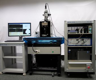
Figure 1 : External view of the apparatus developed |
In recent years, with the increasing need to evaluate the mechanical properties of thin films and microstructures, instrumented indentation to measure indentation depth by pressing a small indenter into the specimen surface is attracting attention. In this indentation testing, an analysis technique is used as a standard method that approximates the specimen as a perfect elastic body and estimates the contact area from the indentation depth (h) of the indenter. However, in a material subject to large plastic deformation and a film–substrate composite made of a rigid substrate, the surface deformation caused by indentation (pile-up, hc > h in Fig. 2b) differs substantially from the elastic behavior of an elastic body (sink-in, hc < h in Fig. 2a). This causes a large error in the contact area estimated from the indentation depth (h), making it impossible to quantify the mechanical properties of the specimen. There has been demand for a new apparatus that will solve this problem and can be used to accurately evaluate mechanical properties by quantifying the contact area between the indenter and the specimen in situ.
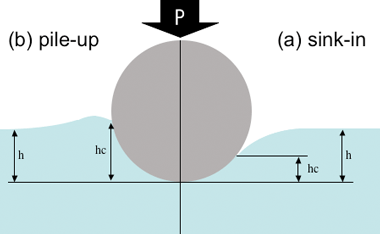 |
Figure 2 : Difference in surface deformation caused by indentation of the minute intender into the surface of the specimen
h: indentation depth of the indenter (depth from the surface of the specimen to the indenter tip); hc: indenter contact depth (depth from the contacting edge of the indenter and the specimen to the indenter tip) |
We have been working with Toyohashi University of Technology to develop a novel test method that uses a small indenter to accurately evaluate the mechanical properties of new materials to which the standard test methods cannot be applied. The small indenter is conventionally used as a mechanical component to indent the specimen through contact of the indenter tip with the surface of the specimen. We have been attempting to develop a novel test method that uses an optomechanically coupled indenter.
A part of this research was supported by "FY2009 Cradling Test," a contracted project commissioned by the Aichi Science and Technology Foundation.
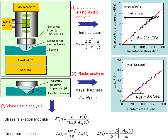
A minute, transparent diamond or sapphire indenter is pressed into the surface of the solid specimen and light is transmitted through the indenter. Changes in the contact area between the indenter and the specimen are measured by observing, in situ, the light transmitted through the indenter using an optical microscope. The instrumented indentation microscope has an indenter drive mechanism, a load detector, and a video analysis capability. The transparent indenter tip is placed at the focal point on the optical axis of the optical microscope. The apparatus can measure, in situ, changes in the contact area as the indenter tip is pressed into the surface of the specimen. The mechanical properties in a micro-region of the specimen can be evaluated directly from the relationship between the contact area (A) and the indentation load (P). With this test apparatus, material properties such as elasticity, elastoplasticity, and viscoelasticity can be measured by changing the shape of the minute indenter tip, the contact speed, etc. (Fig. 3).
The hardness (Meyer hardness, HM) can be obtained from the relationship between the load and the contact area measured by pressing a triangular or quadrilateral pyramid indenter into the specimen at a constant rate. Young's modulus (E) and the yield stress (Y) can be obtained by using a spherical indenter tip under the same measuring conditions. In addition, creep compliance and stress relaxation modulus, which are time-dependent deformation characteristics found in polymers etc., can be evaluated by measuring the time dependence of the contact area with the load controlled to a constant value or that of the load with the contact area controlled to a constant value.
 |
|
Figure 3 : Schematic of the test apparatus, and examples of evaluation |
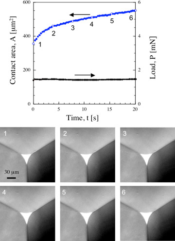
Figure 4 is a creep curve (A(t)) for polyurethane, measured with a triangular pyramid indenter. The six microphotos extracted from a video show the contact surfaces. The whitish part in the center of each picture is the contact area between the surface of the specimen and the triangular pyramid indenter. The figure shows that a contact area increasing over time can be quantified.
 |
|
Figure 4 : An example of measurement in an indentation creep test |
In the next step, we will improve the performance of the instrumented indentation microscope and Sanko Co., Ltd. will commercialize the product.